Description
A – Installation and basic configuration
This part has all general and basic information about installation of controllers, racks, I/O modules, IP configuration, OPC servers, firmware update, project types, and general information about adding function blocks and flexible function blocks.
This part also has troubleshooting information, and the SRF (Service Request Form).
It has the following sections:
- Overview
- Installing
- Setting up
- Configuring the OPC servers
- Configuring strategies
- Adding function blocks
- Adding logic by using flexible function blocks
- Adding I/O modules
- Adding racks
- Troubleshooting
- Appendix (SRF)
B – Technical Specifications
This part has all technical specification of the DFI302 hardware components. They are:
- Controllers – DF51, DF62, DF63, DF73, DF79, DF81, DF89, DF95, DF97 and DF100.
- Ethernet cables, serial cables and cables for racks’ interconnection
- Power supplies – DF50, DF53/DF98, DF52/60, and DF56.
- Intrinsic safety barriers – DF47-12 and DF47-17
- Interfaces – DF58 and DF61
It has the following sections:
- Technical specification for controllers
- Cable specification
- Adding power supplies
- Adding interfaces
C – Modbus
This part has information to integrate systems that use Modbus protocol to the DFI302 automation platform. It has the following section:
- Adding Modbus
D – DF51 Platform
This part has information to create control strategies and redundant systems that use the DF51 controller.
This part also has information about redundant system architecture and its configuration, hot standby redundancy and LAS redundancy. It has the following sections:
E – DF65 Platform
This part has information about the DF65 logic coprocessor which is connected to DF51 (controller of DFI302 automation platform) to improve its capacity for discrete control. The ladder logic and the coprocessor function blocks help and improve the Fieldbus control system.
It has the following section:
- Adding logic configuration by using coprocessors modules
DFI302 – Part E – English Manual (PDF)
F – Configuring strategies with HSE/FF controllers
This part has information to create control strategies that use the DF62 or DF63 controllers. It has the following section:
G – Configuring strategies with HSE/PROFIBUS controllers
This part has information to create control strategies that use the DF73, DF95 or DF97 controllers.
- The DF73 is the HSE/Profibus-DP controller with 2 Ethernet 100 Mbps ports, and 1 Profibus DP channel.
- The DF95 is the HSE/Profibus controller with 2 Ethernet 100 Mbps ports, 1 serial port, 2 Profibus PA ports, and 1 Profibus DP channel.
- The DF97 is the HSE/Profibus controller with 2 Ethernet 100 Mbps ports, 1 serial port, 4 Profibus PA ports, and 1 Profibus DP channel.
It has the following section:
H – Configuring strategies with HSE/DeviceNet controllers
This part has information to create control strategies that use the DF79 controller.
The DF79 is the HSE/DeviceNet controller with 2 Ethernet 100 Mbps ports and 1 DeviceNet channel.
It has the following section:
- Creating a DeviceNet configuration by using DF79
DFI302 – Part H – English Manual (PDF)
I – Configuring strategies with HSE/AS-i controllers
This part has information to create control strategies that use the DF81 controller. The DF81 is the HSE/AS-i controller with 2 Ethernet 100 Mbps ports, and 2 AS-i channels.
It has the following section:
- Creating an AS-i configuration by using DF81
J – Configuring strategies with HSE/Modbus controllers
This part has information to create control strategies that use the DF89 controller.
The DF89 is the HSE/Modbus controller with 2 Ethernet 100 Mbps ports and 1 RS-485/RS-232 Modbus RTU port.
It has the following section:
- Creating a Modbus configuration by using the DF89
K – Configuring strategies with HSE/WirelessHART controllers
This part has information to create control strategies that use the DF100 controller.
The DF100 is the HSE/WirelessHART™ controller with 2 Ethernet 100 Mbps ports, 1 RS-485 port and 1 WirelessHART channel.
It has the following section:
- Creating a FOUNDATION fieldbus strategy by using the DF100
L – Redundancy
To meet the requirements for fault tolerance, system availability and safety of the industrial process, the DFI302 HSE controllers (DF62/DF63/DF73/DF75/DF89) work with a Hot Standby redundancy strategy.
This part has information about installation and configuration of redundant systems which use those controllers.
It has the following sections:
- Adding redundancy to DFI302 HSE controllers
- Adding redundancy with redundant I/O modules R-Series
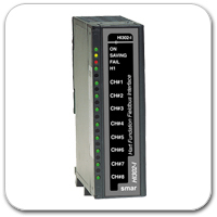
M – Conventional and redundant input/output modules
There are many types of input/output modules available for DFI302 automation platform, designed to fit a broad range of applications in the automation and process control industry.
The available types are:
- Discrete inputs and outputs
- Combined discrete inputs and outputs
- Pulse inputs
- Analog inputs and outputs
- HART inputs and outputs
- Redundant inputs and outputs
The Digital and Analog Input/Output Modules of DFI302 manual has all information about those modules.
DFI302 – Digital and Analogics Input / Output modules for DFI302 – English Manual (PDF)
N – Interfaces for panels
With the Smar’s panel interfaces is possible to eliminate the hard work of making cables, fixing washers and mounting terminal blocks. Just fit the interfaces in the DIN rail and connect the cable. It’s easy and fast!
The interfaces have many features which will fit your application. They were designed for the Smar’s I/O modules.
The Interfaces for Panels manual has all necessary information. This part of manual can be obtained on the Smar’s website (www.smar.com), downloading the file: