Showing all 4 results

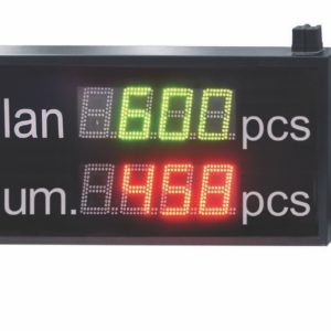
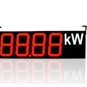
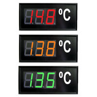
DL21 Numerical Diplay Panel

DL21 numerical display panels are destined to display numerical values read out from a connected device or assigned value through the programming interface in the selected colour by the user. Considering the luminosity of display segments and the housing design they are destined for indoor applications. These display panels find application to display numerical quantities in office rooms, production halls in management points as information about production parameters, machine state, device working state, etc. The displayed value on the display can originate from external devices operating in MODBUS standard, and at the same time it is possible to configure the display to work as “Master” or “Slave”. Moreover, the display enables to connect 10 slave devices to it, and this make possible to fulfill the task of a local point of data acquisition. All data read out from slave devices can be read out through the RS-485 interface. The value can be displayed in the chosen colour (green, red or orange) by the user or the display colour can be changed depending on the indicated value. Moreover, the minimal and maximal indicated value is defined by the user. DL21 display panels are equipped with two RS-485 communication interfaces operating in the MODBUS RTU standard. One of the interfaces is destined to connect slave devices, whereas the second interface is destined to configure the display or to introduce the displayed value ( the display fulfills the part slave in the MODBUS network). The basic display execution includes three digits and the place destined to locate the unit. It is possible to make a display composed of DL21 digits in the configuration defined by the user.

DN1, DN2, DN3 Large Size Numeric Displays

Digital displays of DN type can be applied for the visualisation of essential parameters in automation and measurement processes when supervising the quality or working safety. Information put in a visible place helps in the efficient work in industrial communication, logistics, automation and control technology, and material handling. These displays are destined to be installed in: industrial plants, sports objects, trade buildings and communication areas. The character height ensures a good visibility and reading from a long distance, up to 120 m.

Digit heights: DN1 – 100 mm; DN2 – 200 mm; DN3 – 300 mm. Digital displays are offered in four colours: red, green, yellow and blue.

Basic installations are applied for measurements and indications of: temperature, humidity, time, pressure, flow, rotations, pulses, and also the gas content and material quantity. These DN displays together with an external measuring element or transducer can display any physical quantity and co-operate with external sevices equipped with an RS485 digital output with the MODBUS RTU/ASCII protocol. The configuration of transmission parameters and measuring ranges is made agree with the customer. Each customer obtains a service manual together with the display unit. The standard version includes the digital diode display field and the unit field. The number of characters and the display colour are expressed by the ordering code or defined by the customer. The display field brightness is established automatically in accordance with external conditions. The unit can be selected from the list inserted

DNL2, DNL3 Numerical Digital Display Panel

LED DNL digital display panels are designed for display of digital values indoor: offices, manufacturing plants or production supervision points, providing information such as production parameters, machine condition, device operational status etc.

DNL display panels can be configured with LPCon software application available for free on the website www.lumel.com.pl. DNL display panels are equipped with two RS485 communication interfaces using MODBUS RTU standard. First interface (programming interface) is used for the configuration of the display panel settings or for the input of displayed value (the display panel is a Slave device in MODBUS RTU network) e.g. from the SCADA application or PLC drivers Second interface (object interface) is used for plugging slave devices (the display panel is a Master device in MODBUS RTU network) the display panel gets displayed data from. Display panel configuration allows reading up to 100 registers from slave devices (up to 10 registers per each of 10 devices), so the display panel can act as the local data collection point. All data received from slave devices can be accessed as internal registers of the display panel for the SCADA application or PLC drivers via RS485 MODBUS RTU Slave interface. It is possible to define minimum and maximum displayed value for the display panels. Additionally, the display panel may be equipped with auxiliary measurement input for the measuring of standard analog signal 4..20 mA used in automatics and with output powering external measurement transducers. Basic configuration of the display panel includes one or two fields for readings (4 digits each) and space for the unit placement.

Power Network Analyser

The N100 meter is a programmable digital instrument designed for the measurement of 3-phase, 3 and 4-wire power network parameters in balanced or unbalanced systems. The measured values are displayed on a two-color LED display. The meter enables control and optimization of the power electronic devices, systems and industrial installations. The meter provides measurement of: RMS of voltage and current, active, reactive and apparent power, active, reactive and apparent energy, power factors, frequency, the harmonics of current and voltage /up to 51st/, THD of voltage and current, averaged active and apparent power P Demand, S Demand, averaged current I Demand /15, 30 or 60 minutes/. Voltages and currents are multiplied by given voltage and current ratios of the measuring transformers. Power and energy indications take into account all programmed ratio values. The value of each measured value can be transmitted to the master system via the RS-485 or Ethernet interface. Three relay outputs signal the overflow of the chosen value, and the pulse output can be used for the consumption check of 3-phase active energy. The programmable analog outputs map the assigned parameter. The pulse input can be used to check the counters with the pulse outputs.
There is a galvanic separation between following units of the meter:
–– supply
–– voltage inputs
–– current inputs
–– RS485 interface
–– Ethernet interface
–– pulse input
–– pulse output OC
–– alarm outputs
–– analog outputs